Laboratory Facilities
Wet-Chemical Shaping Techniques
Wet-chemical shaping methods are mainly taken to mean techniques in which suspensions, pastes, or slips based on powder particles are processed into components, structures, or coatings. Techniques which process sols are also included in this category.
IEK-1 has a wide range of thick- and thin-film techniques permitting the manufacture of planar as well as three-dimensional, dense or porous structures.
In addition to these facilities, methods for characterizing the liquid precursors and the layers and components are available. They include particle size analysis, BET surfaces, rheological properties, topography, as well as light, confocal, and scanning electron microscopy, and X-ray diffractometry.
After manufacturing the structures or coating them, various drying and sintering techniques are available (furnaces up to 2000 °C, air, vacuum, inert gases).
Powder Injection Moulding

Two-component injection moulding: Arburg 370U 2K allrounder 700-100-100; processing of two injection moulding materials in one facility by applying an appropriate tool with two cavities.
Tape casting and micro-tape castin


By means of tape casting, extensive two-dimensional continuous structures of various casting thicknesses can be manufactured, depending on the facility used. Sintering thicknesses range between 5 µm and 1000 µm. With this method, substrates for high-temperature fuel cells (SOFCs) and gas separation membranes can be manufactured.
Facilities: SAMA technical facility; micro tape casting facility (currently on order)
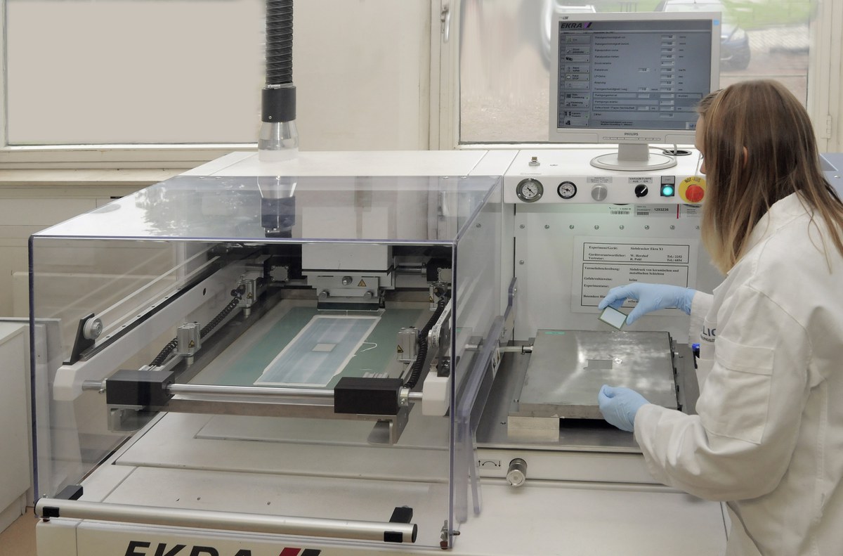
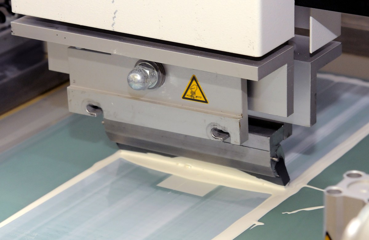
Screen printing
By means of screen printing, ceramic and metallic layers of 10–100 µm thickness can be applied to porous or dense substrates.
The method is currently employed to manufacture the functional layers of solid oxide fuel cells (anode, electrolyte, cathode) and intermediate layers (mesoporous layers) for membrane technology
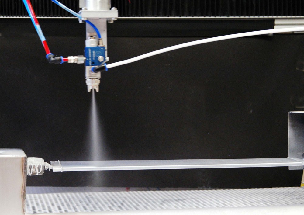
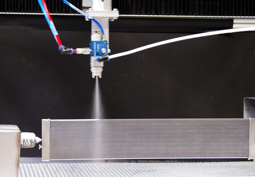
Wet powder spraying
With the wet powder spraying technique (WPS), planar, spherical, and three-dimensional, structured (but not undercut) components can be coated. Through the WPS technique, coating thicknesses of 5 µm to approx. 150 µm can be achieved (multilayer coating). Currently, the metallic interconnects, for example, of solid oxide fuel cells are coated with protection and bond coats by WPS.
Spin and dip coating
Spin coating involves coating planar structures with a sol or a suspension by rotating the component that is to be coated. Attainable layer thicknesses are usually 2 µm or less. During dip coating, the component is either dipped into a suspension or a sol vertically, or by a circular movement. This method is suitable mainly for micrometre-thin layers.

Sintering facilities (inert gas/vacuum)

Manufacturer: Thermal Technology, max. temperature: 1650 °C, max. dimensions: 300 x 300 x 300 mm³, inert gas: Ar, H2, Ar/H2, vacuum, suction device for debindering, heating element: Mo
Manufacturer: Gero, HV-HTK 25 Mo/16-2G, max. temperature: 1600 °C, max. dimensions 250 x 400 x 250 mm³, inert gas: Ar, vacuum, suction device for debindering, heating element: Mo
Thermal Spraying
Thermal spraying involves injecting particulate raw materials in the form of powders or suspensions into a hot gas torch, melting them, and accelerating them towards the substrate. A multitude of process parameters, such as gas composition, gas flow, current, spraying distance, particle size distribution, carrier gas flow, ambient pressure etc. influence the degree of melting and the velocity of the particles and thus significantly affect the resulting microstructure, adhesion, and stresses.Die Heißgas- und die Partikeleigenschaften im Fluge können analysiert werden, um ein verbessertes Verständnis der Prozesse zu erhalten und die Qualität zu sichern.
The properties of the hot gas and the particles in flight can be analysed to result in a better understanding of the processes and to ensure quality.

Plasma spraying
Plasma spraying involves melting particle-shaped raw materials and accelerating them towards the substrate by means of a plasma beam produced by ionizing a gas stream.
Atmospheric plasma spraying (APS) is especially suitable for depositing ceramics, in particular oxide ceramics for thermal barrier coatings.
Burners: Triplex II, TriplexPro-210, Axial III, F4, 9MB, F100 Connex (inner coatings)
Suspension plasma spraying (SPS) is an APS process which involves a liquid suspension as a precursor. This permits the processing of particles in the sub-micrometre range and thus leads to novel, microstructured layers.
Burners: Triplex II, TriplexPro-210, Axial III
Low-pressure plasma spraying (LPPS) and vacuum plasma spraying (VPS) permit ceramic and especially also metallic layers to be produced, while oxygen uptake is avoided.
Burners: F4, TriplexPro-200, O3CP
Low-pressure thin-film plasma spraying (LPPS-TF) represents a further development of vacuum plasma spraying conducted at low pressure. It enables thin, gas-tight layers to be deposited.
Burners: F4, TriplexPro-200, O3CP
Plasma spraying physical vapour deposition (PS-PVD) also takes place at low pressure, but at increased power. With the appropriate powders, depositing novel, columnar structures is possible even from the vapour phase.
Burner: O3CP
Gas dynamic cold spray
Gas dynamic cold spraying involves expanding a moderately pre-heated, compact gas through a de Laval nozzle, which results in very high velocities in the supersonic range. If the powder particles achieve a critical velocity (dependent on the material) they are plasticized upon impacting the substrate, and a firmly adhering, dense coat results. This method is especially suitable for oxidation-sensitive materials.
System: Kinetiks 8000
High-velocity flame spraying
In contrast to plasma spraying, high-velocity flame spraying permits significantly higher particle velocities at comparatively moderate temperatures of the hot gas torch. This means that the process is particularly suitable for wear-resistant alloys and MCrAlY bond coats.
Burners: DJ2600, DJ2700, Hybrid Aircap
Hydrogen-/methane-oxygen process with Air/N2 shroud gas
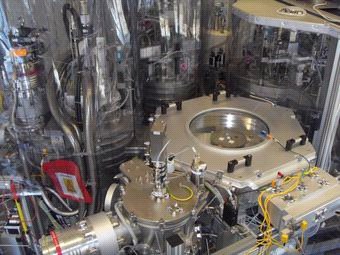
Facility Technologies
There are three different PVD systems and one CVD system at IEK-1 for different fields of application.
PVD Anlage CS 400 ES
The PVD system CS 400 ES (Von Ardenne GmbH) is used for air-insensitive coatings in the field of electrochemical storage and fuel cells. This system allows sputter deposition in direct current (DC)-, pulsed, or radio frequency (RF)- mode and electron beam evaporation, respectively. Both techniques can be enhanced by reactive processing, i.e. in the presence of a gas which can react with the material in the gas phase. For adjustment of the desired morphology the deposition temperature can be raised up to 800°C.

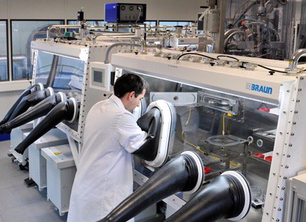
PVD System CS 800 ES
The CS 800 ES PVD system (Von Ardenne GmbH) completes the system technologies of the CS 400 ES and is designed for manufacturing of thin-film batteries. The modular design, consisting of two sputtering chambers and one electron beam evaporation chamber, enables the deposition of complete batteries within the system without removing the samples in between. Thus, contaminations are reduced to a minimum, which enhances the quality of the obtained cells significantly. In addition, the system is connected to a glovebox system. That way even air-sensitive layers can be produced and first analyzes can be carried out without leaving the inert atmosphere.
PVD System CC800/9
The PVD system CC800 / 9 (Cemecon AG) operates by means of high-energy pulse magnetron sputtering. This allows, among others, an improved adhesion of the layers and a homogeneous, dense layer even for complex geometries
CVD System
The CVD system allows the use of metal-organic precursors (MO, so the process is called MO-CVD: metal organic chemical vapor deposition). It further allows processing in which the layers are build up by single atomic layers in succession (called atomic layer deposition: ALD). By using organometallic precursors relatively low coating temperatures (100-300 ° C) can be achieved. The ALD mode can also coat the inner surfaces of porous materials. For this reason diffusion barrier layers, protection layers against oxygen and bio-compatible layers can be applied.

PVD/CVD
Microstructured, more powerful, cheaper: the microelectronics industry has led the way into making highly complex systems better and more affordable by means of mass production manufacturing techniques. Efficient and thus economically viable production is an important aspect for fuel cells and other energy converters as well. This is why IEK-1 relies on vapour deposition processes. There are two basic types of vapour deposition techniques: physical vapour deposition (PVD) and chemical vapour deposition (CVD).

In physical vapor deposition (PVD), a material is transferred to the gas phase, e.g. by evaporation or atomization on an atomic scale. The gas impinges on the samples to be coated and deposits there as a nanometer- to micrometer-thin layer, depending on the duration of the experiment. During the entire coating process - transfer to the gas phase, movement to the samples and condensation on the sample surface - only the aggregate state of the material changes: from "solid" or "liquid" to "gaseous" and back to "solid". However, it remains basically the same material chemically.Chemical vapor deposition (CVD) is different: Here, gases are fed to the samples, which react chemically on their way to the sample or at the sample surface. Some of the chemically reacted substances remain on the surface and form the coating.
Principle
In the process of physical vapor deposition a material is vaporized in atomic scale. The gas impinges the sample and is deposited as thin film, depending on deposition duration in nanometer or micrometer scale. During the whole deposition process – Vaporization – Transfer to sample - Condensation on sample surface – only the aggregate state of the material is changed: from “solid” or “liquid” to “gaseous” and back to “solid”. Typically, the material is not altered during the deposition process.
In case of chemical vapor deposition a gas is transferred to the sample and a chemical reaction during the transport or on the sample surface takes place. Parts of the reacted material stay at the surface and build up the layer.

Scanning Electron Microscopy/Energy-Dispersive X-Ray Spectroscopy (SEM & EDS)

Services and competences
- Qual./quant. Mikrobereichsanalyse (Punkt, Linie, Fläche) mit energiedispersivem Si(Li)-Detektor (EDX), sowie Kathodolumineszenz
- Ergebnisdokumentation in digitaler Form und Bereitstellung im Intranet
- Hochaufgelöste Oberflächen- und Gefügeabbildung im Topografie-/Materialkontrast (E = 0.3 ... 30 keV, Vergr. 20 ... 500 000fach)
Geräte
Anlagen für die Probenpräparation
- Sputterbeschichtungsanlage SCD050 (Au, Pt)
- Leica Sputtercoater EM ACE200 für Pt und Kohlenstoff
- Hitachi IM4000 zur Politur von Bruchfläche und Querschliffen mit Ar-Ionen
Devices for sample preparation
- Sputter coater SCD050 (Au, Pt)
- Leica sputter coater EM ACE200 (Pt, C)
- Hitachi IM4000 polishing device for fracture surfaces and cross sections with Ar
X-ray diffractometry (XRD)


Services and competences
- Qualitative/quantitative phase analysis of polycrystalline materials (deconvolution of superposed interference diagrams of complex phase mixtures, crystalline phases, X-ray amorphous parts)
Phase identification by means of searching and matching the ICDD database (PDF-2, Release 2010) - Determination and refinement of lattice parameters
- Refinement of crystal structures by means of Rietveld analyses
- Determination of crystallite sizes and microstresses
- In situ X-ray diffraction at high temperatures (T = RT-1873 K) in various atmospheres (oxidizing, reducing, inert, vacuum at 10–4 mbar)
- Determination of (local) residual stresses in surfaces and layers (sin2(Psi) method in omega and psi geometry), stress mapping with approx. 1 mm² local resolution
- Orientation determination, texture analysis
- Studies of thin films and coatings
- Result documentation in digital form, accessible on the intranet
Devices
- Theta-2Theta diffractometer with a 66x sample changer (Bruker-AXS/D4 Endeavor), rotatable sample stage, automatic divergence/diffraction antiscatter slits, diverse slit diaphragms, axial Soller slits 2.5°, automatic receiving slit changer, LynxEye line detector, ceramic 2 kW Cu long fine-focus tube
- Universal theta-theta diffractometer for material investigations (PANaytical/Empyrean), 5-axis Eulerian cradle, X-ray mirror, polycapillary half-lens, automatic slit plates, Soller slit 0.04 rad, parallel-plate collimators 0.27°/0.18°, graphite secondary monochromator, Cu/Cr ceramic tubes 2kW
- High-temperature furnace chamber (Anton Paar) HTK 1200N, up to 1200 °C; HTK 16N up to 1600 °C
Special software
- Powder Diffraction File (PDF-2, Release 2010)
- Crystallography Open Database (COD, 10/2014)
- Inorganic Crystal Structure Database (ICSD, online)
- X’Pert Suite (Data Collector 4.3, HighScorePlus 4.1)
- StressPlus, Texture DiffracPlus Evaluation Package V14 (EVA, Search/Match, DQuant, ...)
- Diffrac-AT 3.3B (EVA, Profile, Search/Match) Total Pattern Analysis Solution Software (Topas 4.2)